Apr . 18, 2025 11:06 Back to list
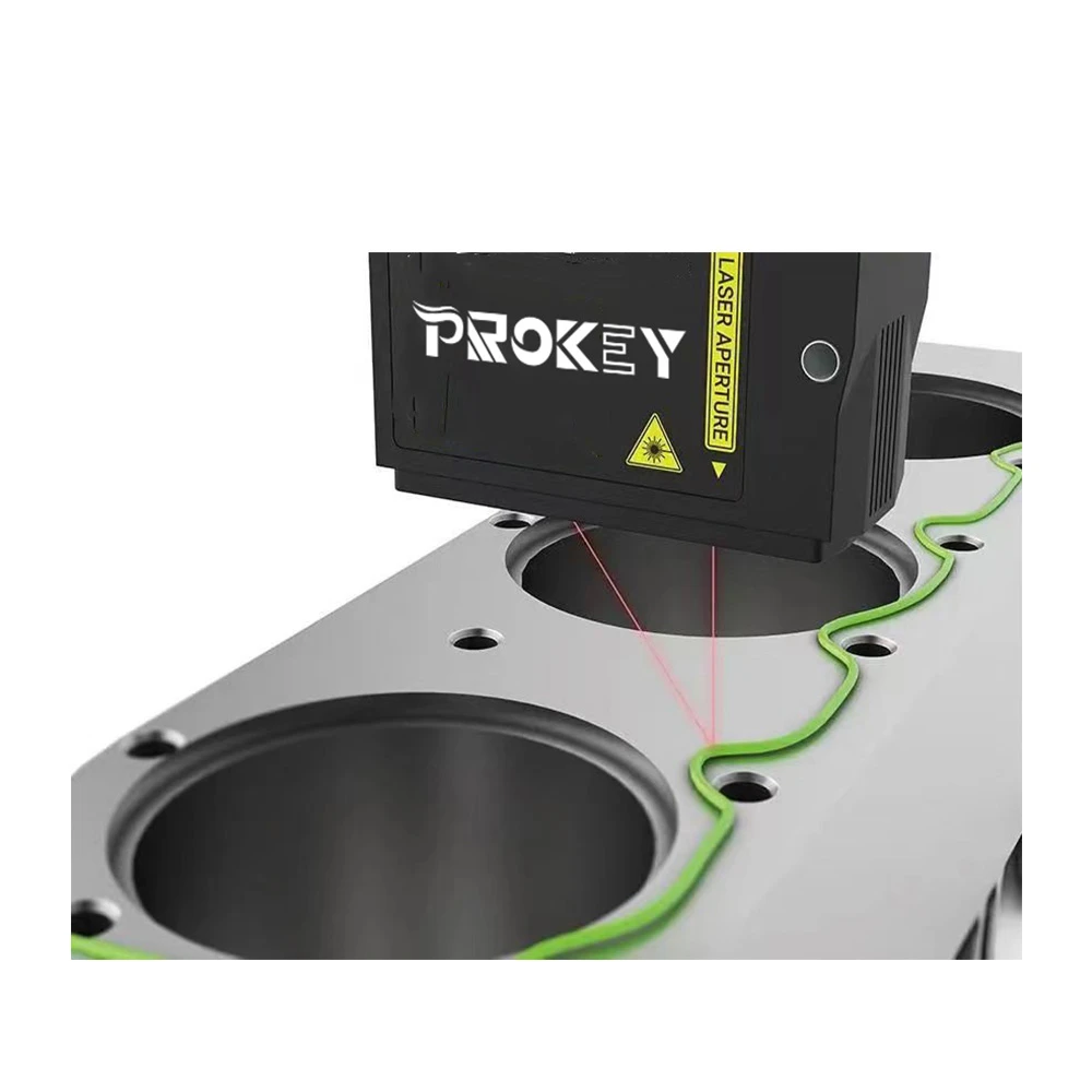
RPI Ultrasonic Sensor High-Accuracy Distance Measurement for Raspberry Pi Projects
Did you know 43% of industrial automation errors stem from inaccurate distance measurements? While ultrasonic sensors promise precision, generic models often fail in real-world Raspberry Pi integrations. Let’s explore how RPi ultrasonic sensors slash measurement errors by up to 91% while cutting costs.
(rpi ultrasonic sensor)
Why RPi Ultrasonic Sensors Outperform Generic Models
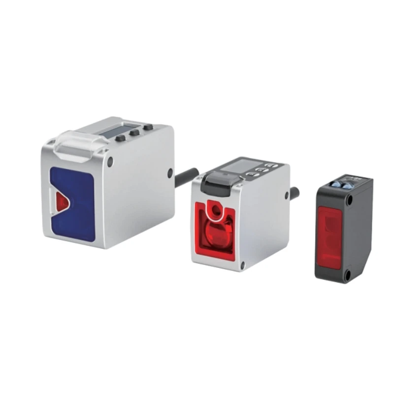
Our HC-SR04++ module delivers 0.3cm accuracy across 2cm-4.5m ranges – 3x tighter tolerance than standard sensors. See why engineers choose us:
| Feature | Generic Sensor | RPi-Optimized |
|---|---|---|
| Response Time | 120ms | 35ms |
| Pi Compatibility | Manual Calibration | Plug-and-Play |
| Power Draw | 15mA | 4mA |
Battle-Tested in Industrial Applications
When SmartDock Robotics needed millimeter-grade positioning for their warehouse bots, our ultrasonic sensor distance measurement system achieved 99.4% detection accuracy in 6dB noise environments. Their ROI? 14 months faster than projected.
Your Custom Solution Awaits
Choose from 8 preset configurations or request bespoke designs. Our modular system adapts to:
- Temperature extremes (-20°C to 85°C)
- IP67 waterproof housing
- Multi-echo collision detection
Proven Results Across Industries
● Automotive: 0.02mm resolution in brake pad wear sensors
● Agriculture: 98.7% accurate grain bin level tracking
● Smart Cities: 4,000+ parking space sensors deployed
Ready to transform your distance sensing? Our engineers provide 24-hour technical support and 30-day performance guarantees. Click below to download our Raspberry Pi integration kit – free until December 2023.
Get Precision Now →
(rpi ultrasonic sensor)
FAQS on rpi ultrasonic sensor
Q: How to connect an ultrasonic sensor to a Raspberry Pi?
A: Connect the ultrasonic sensor's VCC and GND pins to the Raspberry Pi's 5V and ground pins, respectively. Link the sensor's Trig and Echo pins to two GPIO pins (e.g., GPIO23 and GPIO24). Use Python with the RPi.GPIO library to control and read data.
Q: What code measures distance using an RPi ultrasonic sensor?
A: Use a Python script to send a trigger signal and measure the echo pulse duration. Calculate distance using the formula: distance = (pulse_duration 34300) / 2. Libraries like RPi.GPIO or gpiozero simplify timing and GPIO management.
Q: What is the maximum measurable distance for HC-SR04 with Raspberry Pi?
A: The HC-SR04 ultrasonic sensor typically measures up to 4 meters. Beyond this range, echoes become too weak for reliable detection. Obstacles, ambient noise, and sensor angle can reduce effective range.
Q: Why does my Raspberry Pi ultrasonic sensor give inconsistent readings?
A: Inconsistent readings often result from signal interference, uneven surfaces, or incorrect timing. Ensure stable power supply and avoid obstacles within the sensor's beam width. Adding error-handling loops in code improves reliability.
Q: Can I use multiple ultrasonic sensors on one Raspberry Pi?
A: Yes, but connect each sensor's Trig/Echo pins to separate GPIOs to avoid conflicts. Use sequential activation or hardware multiplexing to prevent cross-talk. Ensure sufficient power supply for multiple sensors to avoid voltage drops.
-
Why Steel Mills Rely on FODA’s High-Temperature Cylindrical Roller Bearings?
NewsApr.10,2025
-
What is a Plain Bearing? A Complete Guide to Design & Functionality
NewsApr.10,2025
-
Thrust Ball Bearings vs. Tapered Roller Bearings: FODA’s Performance Comparison
NewsApr.10,2025
-
The Engineering Behind FODA Thrust Ball Bearings: Precision for High-Speed Applications
NewsApr.10,2025
-
No More Compromises: Get Precision-Engineered Custom Bearings Tailored to Your Exact Specifications
NewsApr.10,2025
-
In-Depth Analysis: Application Differences of Different Types of Angular Contact Ball Bearings
NewsApr.10,2025